Motor Revolutions Control System
- This is the teamwork of the two-week course, Design and Practice of Circuit System, in Summer Semester 2018.
- We successfully realized the control of the turn number of a DC motor with the provided analog and digital circuit elements.
- The value of the set revolutions is input through the keyboard (within 5 to 99) and shown in two seven-segment displays, while the value of current revolutions is shown in another two seven-segment displays.
- The motor will finally rotate to the revolutions whose value is equal to the input number.
- The motor can either rotate forward or backward to reach the set value.
The detail of some essential parts is discussed below.
The Judgement of the Direction of Rotation
- Two optoelectronic switches identify the current rotate direction of the motor.
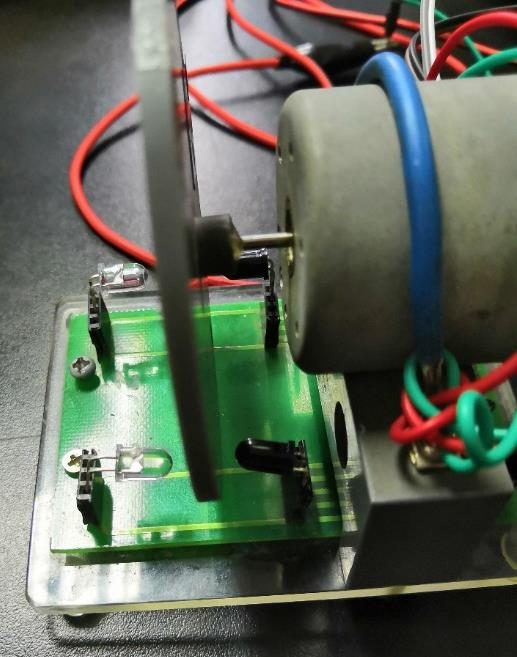
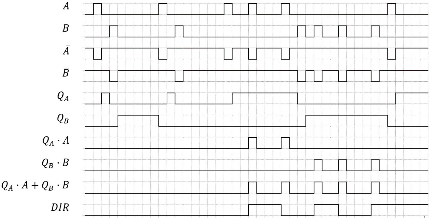
- Limited by the components, we chose to observe whether the hole on the rotary table passes the other switch between the two nearest passing of a same switch. Suppose from now on, the hole passes switch A first, followed by it passing switch A again without passing switch B, then we can decide that the motor changes its rotate direction.
- Based on that theory, the sequence chart of our circuit is shown below, where A turns into high level when the hole passes A, and B the same.
The Speed Control of the Motor
- The motor is driven by PWM wave.
- The duty cycle of the PWM wave is decided by the resistence in the circuit, which can be determined by the relative size (decided by CD4585) of the set value and the current value of the revolutions.
The Chip in the Circuit
- CD4081 AND gate
- CD4071 OR gate
- CD4069 Inverter
- CD40106 Schmitt trigger
- CD4013 D-flip-flop
- CD4510/CD4516 Decade counter/Hexadecimal counter
- CD4511 BCD-seven-segment decoder
- CD4066 Analog switch
- CD4585 Comparator
- LF353 OPAMP
General Circuit Diagram
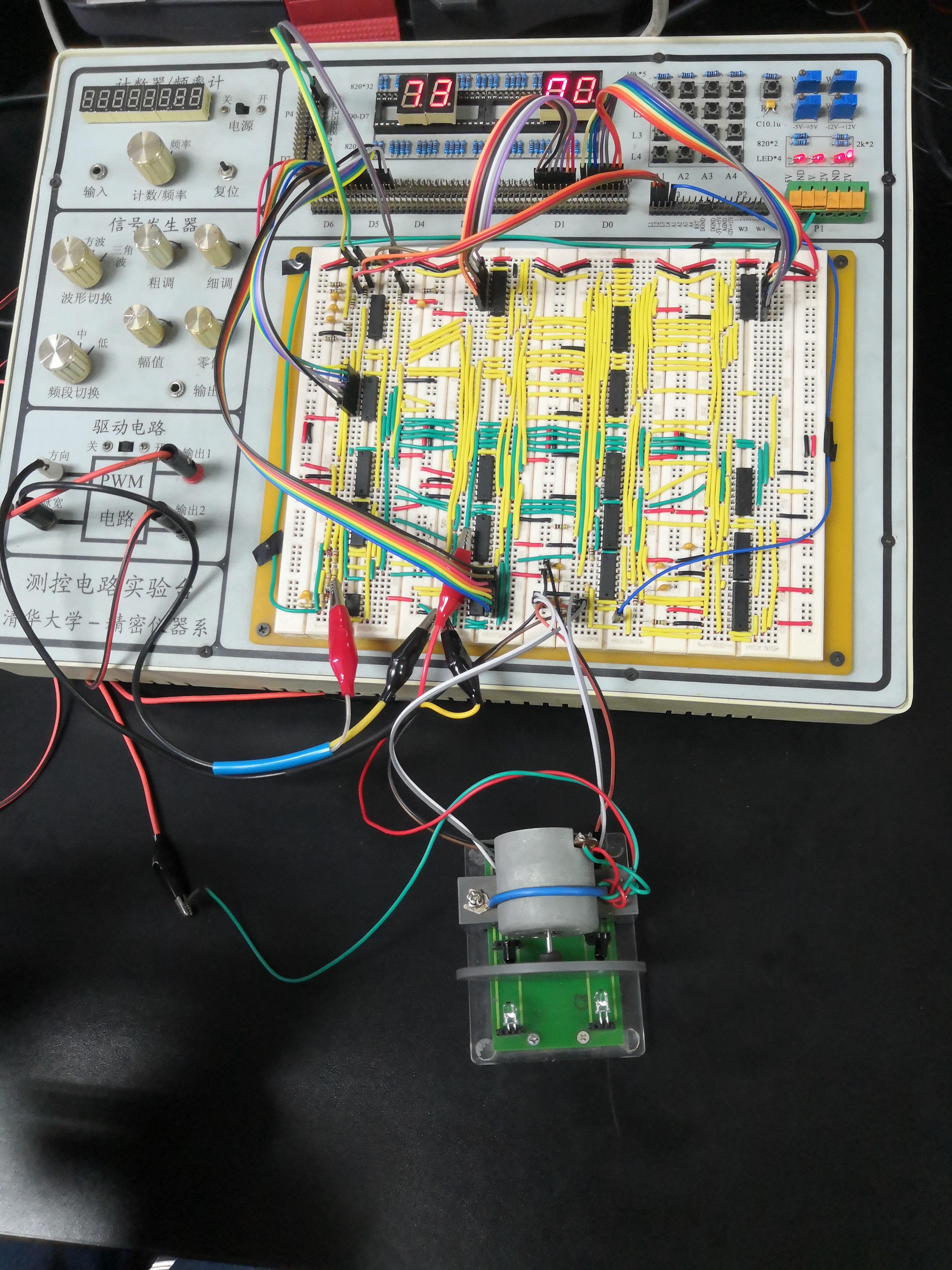
- Besides, when we turned the experimental box upside down after testing, nothing falls! Congrats!
Acknowledgement
- Thank my teammate, Jiahao Qiu, who undertook the number input and display and the PWM wave generating work.